Why Radiant Cooling System
To understand why we need to use Radiant Cooling, answer the following four questions.
- What is the merit of cooling a place using AIR, a good insulating medium, with low thermal capacity?
- If you suffer a burn on your hand, will you put your hand below a fan or will you rather put your hand under tap water?
- If you want to empty a tank, do you pump it out or would you rather drain it?
- Which heat transfer process would you choose: A or B?A: linearly proportional to the temperature difference (i.e. doubling ∆ T = 2 x heat transfer rate)B: proportional to 4th power of temperature difference (i.e. doubling ∆ T = 16 x heat transfer rate)
- Radiant Cooling System uses water as a medium to cool the occupied spaces of people and the conventional air-conditioning system uses air to create a cooling effect.
- The system drains heat by using less energy and more energy efficient, whereas, the conventional system pumps air by spending electricity
There are three reasons why water is much more efficient than air as a heat transfer medium. Water is approximately 20 times the thermal conductivity of air, the specific heat capacity of water is four times that of air and finally, the density of water is much more compared to air.
| Thermal Conductivity (W/mK) | Specific Heat Capacity (W/kg.k) | Density (kg/m3) | |
| Air | 0.03 | 1.004 | 1.225 |
| Water | 0.6 | 4.18 | 1000 |
Water presents a significantly higher heat transfer capacity:
- the multiplier of specific heat capacity and density for water vs. air is ~ 3400 (heat absorption per unit volume)
- the thermal conductivity multiplier for water vs. air is ~ 20 (heat transfer per unit area per unit thickness)
| Medium | Cooling Capacity | Flowrate Required | Power Required |
| Air | 100 TR | ~ 40,000 cfm | 22 kW |
| Water | 100 TR | ~32 cfm | 3.7 kW |
What is Radiant Cooling System?
Radiant Cooling is based on the physical principle, that bodies with varying temperatures exchange thermal radiation until an equilibrium is achieved. The principle of radiant cooling has been around in nature, and human beings have been using this principle knowingly or unknowingly for ages.
Radiant cooling systems work by circulating chilled water through a network of polymer pipes installed in floors, walls or ceilings. This network of pipes can turn the floors, walls and ceilings of a conditioned space into cooled surfaces that evenly absorb heat energy. Radiant cooling works best in a tightly sealed building that integrates radiant with a downsized forced-air system to meet the building’s fresh air requirements.
Functioning of Radiant Cooling System

There are three types of radiant cooling systems:
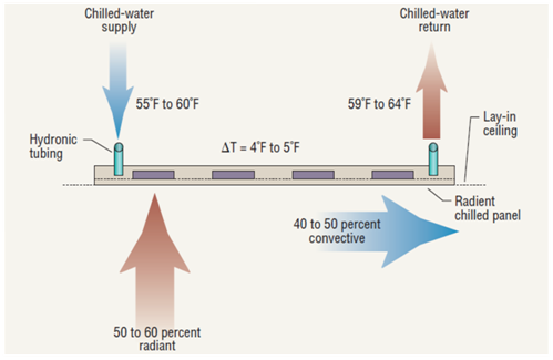
- Chilled ceiling/floor/slab/wall – They work by means of convective and radiant heat transfer, and induce air movement. The sensible cooling capacity is approximately 24 BTU/hour per sq. ft. of the beam. Chilled ceilings lack the ability to control the humidity of a room and must be paired with a ventilation system.
- Passive chilled beam – Passive beams use a pipe surrounded by a coil in order to form a radiator system, often used in conjunction with an under-floor air distribution system. The cooling capacity is approximately 400 BTU/hour per linear foot of beam. The system does not have any method for maintaining the humidity of a room and must be paired with a ventilation system.
- Active chilled beam – They have a ventilation air duct through the chilled beam. The ventilation air must be dehumidified upstream to avoid condensation potential at the chilled beam.
Radiant cooling cools a floor or ceiling by absorbing the heat radiated from the rest of the room. Cooling the ceiling is usually done in homes with radiant panels. Aluminum panels suspended from the ceiling, through which chilled water is circulated. Panels must be maintained at a temperature very near to the dew point within the house, and the house must be kept dehumidified.
Radiant Cooling from Ceiling

- Cooling the building mass (floor, ceiling, walls etc.) forms a heat sink to absorb energy from heat sources at a higher temperature through radiation
- Eventually, air temperature also reduces due to conduction & natural convection
- The water is chilled water with a conventional refrigeration system
Science Principle
The radiant heat flow between two internal surfaces is based on the following:
- Emissivity of heat emitting surface: the ratio of radiant flux of a body to the radiant flux of a perfect black body.
- View & Angle Factor between any heat emitting surface and the other surface; view and angle factor represent the correlation of geometrical shape, size (area) and the distance between two objects (e.g. person & room surface). The sum of angle factor between the person & all room surface is equal to 1.
In the below example:
- approx. 50% of the body is shielded by the chair
- window ~ 15% of the field of view
- fire ~ 3% of the field of view
- walls and ceiling the rest
To achieve a weighted average of the temperature of all surrounding surfaces, the fire must be commensurately hot to compensate for other lower temperature surfaces.
Image showing temperature of surrounding surfaces

Whenever there is a temperature difference between two objects, both objects will attempt to equalize the temperature
- The energy transfer required to approach equivalent temperatures occurs through radiation, conduction, and convection
- Radiant energy is infrared energy that travels from “hot” to “cold” through space, without heating the space itself
People are exothermic heat generators. Heat emission from the human body occurs via four modes of heat transfer:
- Radiation (~45%)
- Convection (~30%)
- Evaporation (~20%)
- Conduction (~5%)
– Our bodies radiate heat to any surface in line-of-sight which is cooler than our own surface temperature (85 – 90°F / 29 – 32°C)
– Humans feel most comfortable when they can regulate at least 45% of their heat emission through radiation
– Reducing surrounding surface temperatures draws more heat from our bodies via radiation
Radiant heat transfer capacity of a typical human body

Radiant heat transfer capacity between two objects

From years of adjusting thermostats, we have been conditioned to believe that air temperature alone translates to comfort, but this is not necessarily true.
We have to consider:
- Air temperature – space’s air temperature, monitored by the thermostat as “setpoint temperature”
- Mean radiant temperature (MRT) – weighted average of the temperature of all surrounding surfaces, weighted by spherical angle and the thermal emissivity of each surface
- Operative room temperature – Weighted average of mean radiant temperature and the conditioned space’s air temperature
The operative temperature is what we perceive on our skin in a room and what is most important to consider when specifying a radiant system. Higher air temperature set points during the cooling season and lower set points during the heating season are possible with radiant systems. Boundaries for thermal comfort according to ASHRAE Standard 55:
Body heat production and environmental heat exchange studied by ASHRAE

Operative temperature:
- Summer period @ 50% RH: 75 – 80°F
- Winter period @ 30% RH: 70 – 77°F
- The range of the floor temperature: 66 – 84°F
At this operative temperature, the maximum percentage of people will have thermal comfort and a reasonable percentage of less than 10% of people will feel dissatisfied.
A lower Mean Radiant Temperature increases the radiant heat loss from the human body:
- Surfaces are cooler with radiant cooling
- Human body radiates more heat to floors, walls, and ceilings
- Indoor air does not have to be as cool for equivalent comfort
- Indoor air temperature setpoint is elevated, or operative temperature may be too low
- We typically use setpoint temperatures above 75°F for radiant cooling applications
- With cooler surface temperatures, the air can be warmer without causing discomfort, saving energy.
A radiant cooling system works with the reverse energy transfer process, providing a comfortable environment by absorbing heat from the space. In cooling mode, the heat transferred into the floor is removed from the space via the circulating fluid.
Spaces with 100% forced-air systems have higher mean radiant temperatures due to solar gains and office equipment. Occupant turns down the air setpoint, trying to counter radiant loads using more cooler air. This requires more air movement, inefficiently countering a high MRT. With an air-based system in combination with a radiant cooling system, surface temperatures are naturally lower. This increases the heat emitted from the occupant to cool surfaces via radiation and occupant feels comfortable within the space, which removes the need for a lower air temperature and/or increased air flow. Most efficiently counters heat loads.
Engineering Principles
- Cooling load of space comprises of sensible load and latent load
- Radiant heat from solar radiation on the building envelope (roof, walls) is a significant part of the sensible load
- In dry climates, sensible load ~ 90%, latent heat load ~10%. While in humid climates, ~ 80% sensible load and ~ 20% latent load
- Radiant Cooling caters only to sensible heat load; latent heat load (related to moisture content) requires dehumidification by conventional HVAC system or dehumidifiers
- In most Indian climatic zones, radiant cooling can address 40 to 50% of the sensible heat load (at the internal air temperature of 240C to 250C); residual load can be catered to by conventional AC system
Radiant Cooling and Heating System Schematic Diagram
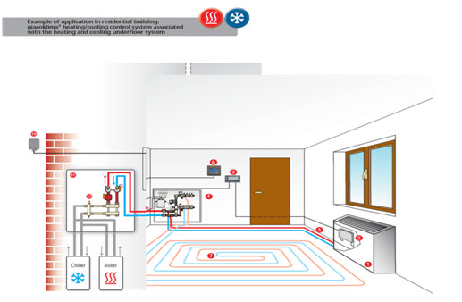
Cold water circulation through PEX pipes
- Radiant Cooling can significantly downsize conventional HVAC system sizes; if not able to replace them entirely
- Radiant Cooling capacity depends on the radiant surface area
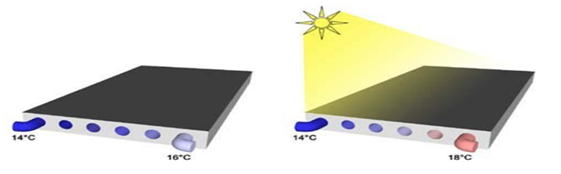
- Radiant Cooling surfaces mounted in perimeter zones effectively mitigate cooling load due to solar radiation by direct absorption of incident solar radiation; the system’s output can scale to higher outputs in proportion to peak solar gains
Radiant cooling surfaces mounted in perimeter zones
Operation Mechanism
- The Radiant Cooling system consists of plastic pipes concealed in ceiling/false ceiling/floor/slab/walls.
- Chilled water is circulated through the concealed pipes.
- Plastic pipes can be covered with all usual building materials.
- Perceived temperature: a numerical average of mean radiant temperature of surrounding surfaces and the room air temp.
Radiant Cooling System Components:
- PEX (cross-linked polyethylene) pipes, embedded in a slab or flooring screed
- Cold water flows through these pipes transforming the surrounding surface into a cold surface that serves as a heat sink for radiant heat
- PEX pipes possess an anti-oxygen barrier to attenuate oxygen entry and thereby avoid scaling
- Manifold (like ‘switchboard’) to which the main cold water supply and return lines are connected and from where water is supplied to PEX pipe circuits
- Controls to ensure the surface temperature is always above Dew Point Temperature of surrounding area so that condensation does not occur (eg. for an air temperature = 26 0C, Dew Point Temperature at 60% RH ~ 17.6 0C)
- There also a small air handling unit to control humidity.
Radiant Cooling System Components

Small air handling unit to control humidity

Radiant Cooling System Configurations:
- Radiant cooling can be integrated within any type of surface depending on feasibility for a specific application
- Ceiling based radiant cooling is the most energy-efficient configuration; the direction of convection currents developed are congruent with the temperature gradient i.e. cool air sinks downwards and facilitates upwards movement of warmer air from heat source located below
Radiant Cooling System Configurations

- Thermally Activated Slab (TAS)
- Without insulation underneath
- Bi-directional: Heated/cooled floors and ceilings condition spaces above and below.
2. Radiant Floor Cooling & Heating (FCH)
- With insulation underneath to cool space above
- Heated/cooled floor
- Uni-directional
Radiant Floor Cooling and Heating

3. Radiant Ceiling Heating & Cooling (CHC)
- Installed directly below structural ceiling
- Panels with embedded pipes or pipes attached to ceiling and covered with plaster
Radiant Ceiling Heating & Cooling

4. Radiant Wall Heating and Cooling (WHC)
- Panels with embedded pipes or pipes attached to the ceiling and covered with plaster
- Small diameter pipes are attached to walls then “plastered” over
- Pipes may be run from the floor as the same circuit or a distinct circuit can be installed
Radiant Wall Heating and Cooling

The Operation Schematic includes:
Operation Schematic Diagram of Radiant Cooling

The design process includes:
- Building/Zone Heat Load Calculation
- Heat Transfer Calculation
- System Sizing and Performance (Cooling Output, Surface Temperature, Heat Transfer Area)
- Hydraulic Design
- Ventilation (AHU, Ducts) and Dehumidification (VCR/VAM) System Design
Installation Process
The pipes can be embedded in the slab.
Installation of Thermally Activated Slab Cooling & Heating

The pipes can be installed in the middle of the slab when both upper and lower floor have to be cooled. The pipe can also be installed closer to the ceiling.
Section view of Thermally Activated Slab Cooling & Heating

The pipes can be installed in plastering on the ceiling instead of being embed in the slab.
Section view of Radiant Ceiling Heating & Cooling

The pipes can be laid to form different zones.
Manifolds of Radiant Floor Cooling & Heating

BENEFITS:
- Energy and Operation Costs
- Specific Heat Capacity of water ~ 4 times that of air: for the same flow rate, 4 times more heat can be removed by using water than by using air.
- Air flow rate and Fan power consumption reduced drastically: To remove 1 kW of heat from a room, an AC needs ~140 W of fan power. For the same load, a radiant system needs ~ 3 W to run the circulation pump.
- Reduced energy loss due to duct leakage & fan motor heat loss
- Lower life cycle cost compared to conventional, due to decreased maintenance
- With every degree increase of room temp of the AC system, about 6% of energy is saved
Comparison of parameters between AC System and Radiant Cooling System

Higher chiller operating temperature improves COP by ~ 30%
Performance of COP at higher chiller operating temperature

2. Capital Costs & Saleable Space
- It has lower first costs attributed to integration with structure and design elements and a smaller chiller requirement.
- Low air volume and hence duct sizes are significantly reduced.
- Fewer Air Handling Units; in some cases, only treated fresh air units may be
- AHU room in the building can be eliminated
- The additional floor can be added in the same FSI / Building Height due to vertical-space saving from eliminated ducts
- Space-saving from smaller chiller size
3. Other
- Space heating can be done using the same system
- Absolutely noiseless & vibration free
- Does not produce any draft.
- Provides uniform temperature
- Surface temperature or supply temperature is always above dew point and hence, there is no chance of condensation
CONSTRAINTS:
- The potential for condensate formation on the cold radiant surface hinders their application
- Surface temperature should not be equal or below the dew point temperature in the space
- The supplementary air-conditioning system is required: for the removal of the latent load (moisture removal) and fresh air
- In dry regions, the radiant system can work independently for most times of the year (except during monsoon time)
- Commercial Area – office spaces, schools, and few applications in hotels.
- Residential – in homes, in areas where humidity is less.
- Industry- Capillary tubes may be used for an industrial application, as well as a fire suppression system
- Hospitals and Laboratories – Radiant cooling can be effective to maintain a clean environment in hospitals and laboratories. It provides a silent, draft-free, thermally stable environment for sedentary patients.
Indian Institute of Tropical Meteorology (Pune, India)
Under Floor Installation at L&T Hajira (Surat, India)
Design Brief:
- Site Location: L&T Hazira Surat, Gujarat
- Climate Area: Hot and Humid; high Latent Heat Load
- Design Conditions: Indoor design temp.: 25℃, Relative Humidity: 60%
Solution:
- Radiant Cooling was used for the ground floor
- Insulated ground floor slab mitigated loss of cooling effect
- Latent Load and residual Sensible Load was met by Air Conditioning System
- The underfloor cooling system was installed in areas containing workstations connected to electrical conduits in the floor
- Required intricate routing design, floor surface marking, and coordination to ensure PEX pipes were not punctured during electrical ‘raceway’ installation
Heat Load Analysis

Impact of Radiant Cooling on Total Power Requirement

Impact of radiant cooling on conventional HVAC system:

Impact of Radiant Cooling on Conventional HVAC System TR

Impact of Radiant Cooling on AHU Power

Impact of Radiant Cooling on Chiller Power

Infosys (Hyderabad, India)
- Infosys, constructed – 1st radiant cooled commercial building in India in its Hyderabad campus.
- Total built up area – 24,000 sqm.,
- Significant feature – split into 2 identical halves – one with conventional air conditioning (high efficiency and surpassing ASHRAE standards by about 30%) and the other with radiant cooling.
Infosys Hyderabad Campus

Savings achieved in Infosys Hyderabad Building

View Radiant Cooling resources for Architects and for Engineers.
| Manufacturer | Product | Contact |
| Giacomini India | Radiant Cooling | Phone: +91 22 2167 6767 Mobile: Naitik Shah, 9321011122 Email: naitik@giacomini.in Website: https://www.giacomini.com/en Address: G-3, Neel Madhav, Nr. Navneet Hospital, V.P. Cross Road, Mulund (west), Mumbai, Maharastra-400080 |
| Oorja Energy Engineering | Radiant Cooling | Phone: +91-7842095103 Mobile: Mr. Madhusudhan Rao, 9000332828 Email: madhu@oorja.in Website: http://www.oorja.in/structure-cooling/ Address: Plot No. 30, Lane No. 14, Phase – II, IDA Cherlapally, Hyderabad, Telangana – 5000051. |
| Uponor | Radiant Cooling | Mobile: Mr. Fenil Kapadia 9821970343 Email: fenil.kapadia@uponor.com Website: https://www.uponor.com/products/ceiling-heating-and-cooling/comfort-cooling-panel- |
| Unitech Enterprise Building Solutions | Radiant Cooling | Phone: +91 22 2387 6666 Email: info@unitechenterprise.com Website: https://www.unitechenterprise.in/radiant-cooling-system.html Address: 01/202, Parekh Market, 39 Kennedy Bridge, Opera House, Mumbai - 400 004 |
| Airtech India | Radiant Cooling | Phone: 020 4008 5961 Email: sales@airtechindia.com Website: http://www.airtechindia.com Address: 03 Mangalmurti complex 990 Shukrwar Peth Hirabaugh Chowk, Shukrwar Peth, Pune, Maharashtra 411002 |
| REHAU Polymers | Radiant Cooling | Phone: +91 114848-5600 Email: infoindia@rehau.com Website: www.rehau.co.in Address: 88, 2nd Floor, Furniture Block, Kirti Nagar, 110015 New Delhi |
RELATED SUSTAINABLE COOLING TECHNOLOGIES
Evaporative Cooling
Structure Cooling