What is the Structure Cooling System?
The most evolved three-pronged technique to achieve thermal comfort using no energy is to:
- Create barriers: trees, verandahs, hollow walls, stone screens
- Build massive structures and use them as thermal capacitors: thick walls and high ceilings
- Drain out the stored heat: water bodies in contact with the plinth and by special plasters that promoted radiation to the sky
- A modern manifestation of above features which adheres to the techniques but enhances the technology is Structural Cooling.
Inspired by the ancient buildings, a direct structure cooling system addresses the heat stored by the structure. This system removes the heat in the structure by way of a refrigerant/water flowing through pipes. If required, a conventional AC may be used in conjunction with this system; the load on it will be significantly reduced. The system has the following basic components-
Piping: Pipes have inlaid through the slabs of the building. The distance between successive pipes is chosen based on the type of material used and its ability to bend. This distance and the material of the pipe govern the conductance of unit length of the piping. The refrigerant/water flows through them and absorbs heat from the structure.
Storage tank: This tank stores the refrigerant/water that is pumped to the slab using a submersible pump. It is covered with a sheet of rubber, plastic insulation and reflective material to minimize the gain of heat by incident radiation. The refrigerant/water, after passing through the slab, returns to this tank.
Cooling System: The cooling system cools the refrigerant/water returning from the slab before it is sent back to the storage tank. The cooling system can be active refrigeration type or passive type.
Pump: There is a submersible pump installed in the tank that pumps refrigerant/water from the tank to the slab. This pump governs the mass flow rate of fluid in the system. It is also the main power consuming device in a passive system.
- Suitable for the high mass, uninsulated buildings primarily built in India.
- Occupants feel comfortable in spaces if surrounding surface temperatures are below body temperature: the body loses heat spontaneously
- Works on radiation and convection heat transfer eg. in ceiling cooling, 50% cooling output through convection, 50% through radiation
- Not just about providing a cool-surface to radiate heat into (i.e. radiant cooling), it directly ‘drains’ solar heat load from the structure
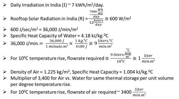
Calculation showing thermal capacity of air and water
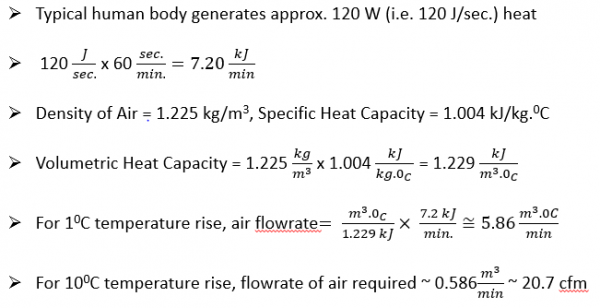
Radiant heat transfer capacity of a typical human body
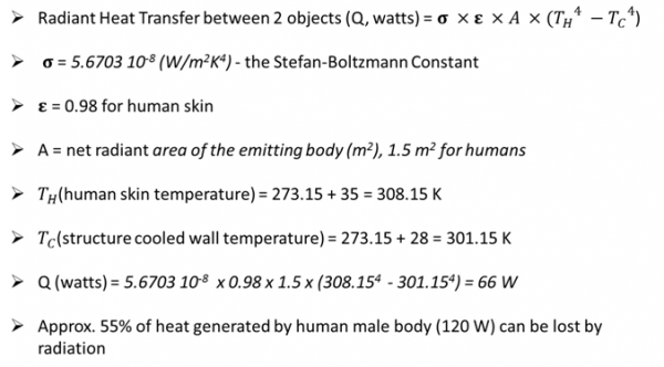
Radiant heat transfer capacity between two objects
Science Principle
- At skin temperature or above, the only way to lose body heat is by perspiration
- At low MRT, most body heat is lost by radiation& convection
Body heat production and environmental heat exchange studied by ASHRAE
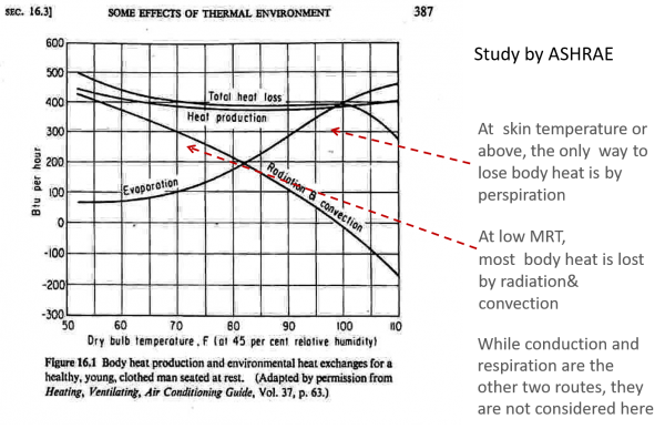
- Indoor building surface temperatures are at or above the human skin temperature during the day and late into the night.
Indoor building surface temperatures are at or above the human skin temperature during the day and late into the night

- Building Designers must keep the MRT well below the skin temperature
Operation Mechanism
- Step 1: Pump in the insulated, partitioned tank circulates water.
- Step 2: Water picks up heat from the slab
- Step 3: Returning water is cooled by a fan cooled heat pipe on its way to the tank.
- Step 4: Returns to the same tank, closing the loop
- Step 5: At night, radiative panel lowers tank temperature by direct radiation to the sky. Cooled water ready for the next day’s cycle.
Schematic diagram of piping of Structure Cooling
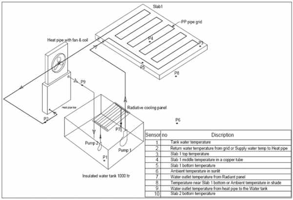
Step 1: Lay 25mm dia. corrugated polypropylene pipe in a joint-less continuous loop over the bare slab.

Step 2: Cover the pipe loop with a 50 mm screed/ Water proofing to be done over it.

Step 3: Connect the submersible pump in the tank to the loop, heat pipe and back to the tank

Step 4: One square meter sheet of aluminium. With a serpentine copper coil attached to it. Coated with a barite rich paint resulting in high emissivity.

- Impedes solar heat gain from roof and floors by absorbing it before causing thermal discomfort to occupants; thermodynamic heat sink.
- Able to maintain floor temperature below human skin temperature on hottest summer day.
- Cool floor and ceiling reduce (i.e. low Mean Radiant Temperature) enhances comfort for the same temperature and humidity.
- During night time, further cooling of structure through night sky radiation.
- Closed circuit; no evaporation and no loss of water.
- Only active elements are a pump & fan; use negligible energy that Solar PV Panel can address.
- All components are locally available; no prohibitive patents
- Pipes do not have to be embedded while casting slabs; allows retro-fit.
- Approximate cost benefit analysis
Cost benefit analysis of Structure Cooling

Green Space Realtors
Thaker Industrial Estate, Mumbai
A 200m length of corrugated polypropylene pipe was laid on top of a concrete slab in a joint-less loop. It was then covered with screed. The water from the insulated tank is circulated through the loop by a submersible pump and returned to the same tank. Returning water is cooled by a fan cooled heat pipe on its way to the tank. At night, the radiative panel lowers the tank temperature by direct radiation to the sky. A data logger records the temperature from ten temperature sensors.
The system was able to maintain a below slab temperature near 30 °C, without losing any water and using the negligible power that can be easily supplied by a solar PV panel. If a lower temperature is desired, then a mechanical evaporative or refrigerated cooling system could be added.

Veer Savarkar Rashtriya Smarak
The administration block of this building was modified to accommodate a D.S.C system in December 2012 and since then the thermal performance is being recorded. The one story tall building is attached to a multi-storeyed block on the west side; hence it is shading from the west. The large roof of 554 sq.m has multiple uses such as administration offices, reception, waiting lobby, library, gym and bathroom block.
Layout of water circuit and components from D.S.C system in V.S.R.Smarak
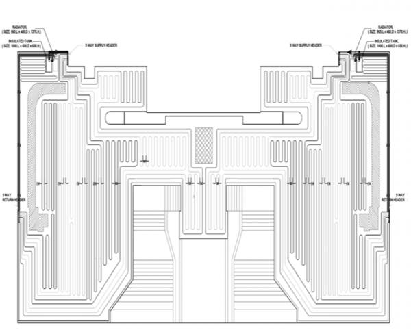
Due to the symmetrical plan of the roof, a pipe layout grid was made for one part and mirrored for the second part. A total of 9 loops on each slab add up to a 1700m polypropylene pipe network covering the whole of the terrace. This is managed and supplied by one radiator, one insulated water tank of 500 liters capacity and one-way distribution and return header per slab. Five thermal sensors log into one central data logger located at the reception tracks. These sensors log the temperature of each slab’s top and bottom. Another thermal sensor reads the ambient temperature. An automated mechanism keeps the tab on the return water temperature and automatically turns on the radiator if its temperature rises above 30°C.
Insulated tank and chiller unit
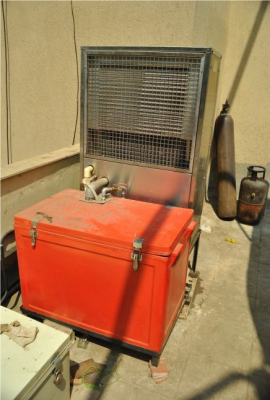
View of chiller unit
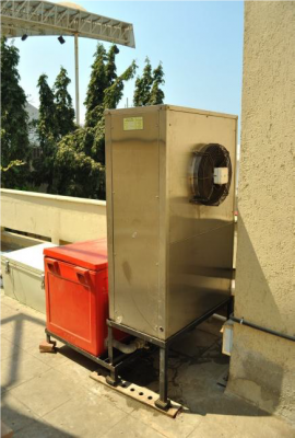
Return water unit collecting water from 9 circuits and leading it back to the chiller
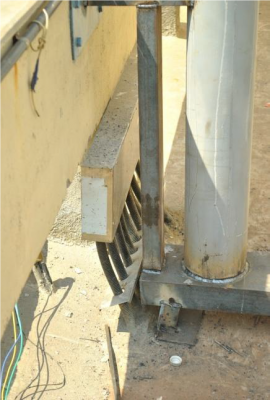
Distribution unit from where the 9 circuits in each slab
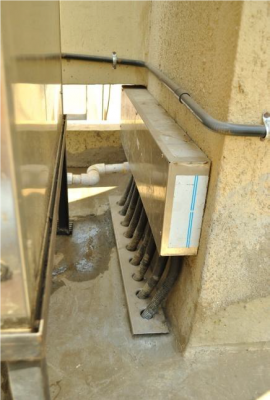
View Structure Cooling resources for Architects and for Engineers.
| Manufacturer | Product | Contact |
| Panasia Engineers | Structure Cooling: Therm-O-Drain | Mobile: Mr. Udit Shah, 8286002222 Email: Ho@panasiaengineers.com Website: https://www.panasiaengineers.com Address: NM Joshi Marg, Shastri Nagar, Adarsh Nagar, Jacob Circle, Mumbai, Maharashtra 400011 |
| Oorja Energy Engineering | Structure Cooling | Mobile: Mr. Madhusudhan Rao, 9000332828 Email: madhu@oorja.in Website: http://www.oorja.in/structure-cooling/ Address: Plot No. 30, Lane No. 14, Phase – II, IDA Cherlapally, Hyderabad, Telangana – 5000051. Phone: +91-7842095103. |
| Uponor | Structure Cooling: TABS | Mobile: Mr. Fenil Kapadia 9821970343 Email: fenil.kapadia@uponor.com Website: https://www.uponor.com/products/ceiling-heating-and-cooling/tabs |

